Fuses, Connections and Wires
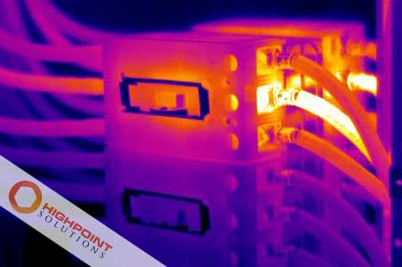
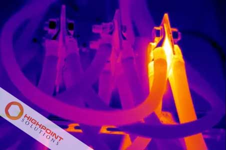
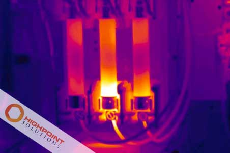
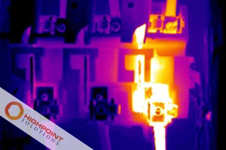
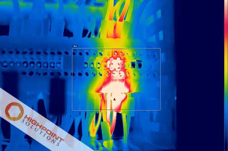
Start by scanning electrical connection points where wires join to devices, or devices plug into each other. Overtight, loose, and corroded joints increase resistance, and hence heat. The thermal image is therefore ‘hottest’ at these points, while ‘cooler’ on either side and will generally display a thermal gradient typical of a “hot-spot”. Broken and below-specification cables can also emit abnormal heat.
A circuit breaker that reads noticeably hotter during thermal imaging is under exceptional load. However, this is usually due to a problem elsewhere in the circuit. Trace the network in the wiring diagram to identify potentially defective devices and scan them. An abnormally cool circuit breaker suggests it has failed. Ask a qualified electrician to investigate further.
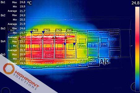
Remember to look for differences between similar devices and similar thickness wires. If they do not emit approximately matching heat when viewed through a thermal imaging camera, then you may have found something wrong. In a nutshell, that’s the purpose of scanning for electrical problems safely with thermal imaging as we describe here.
Imbalances in 3-Phase Networks
Motors, their controllers and other electrical equipment are unreliable when operating on unbalanced voltages between phases. Any variances above 4% are cause for concern, and require resolution. To check for three-phase imbalance, begin by capturing images of distribution panels, drives, switches and so on.
Open each compartment on a motor control centre. Scan breakers, bus bars, controllers, contactors, disconnects, fuses, feeders, starters, relays, and transformers for relative overheat. Much of the information elsewhere in this article applies to motor control centres too.
Upload the electrical switchboard thermography images to a computer. Compare the three phases side-by-side to look for inconsistencies in scanned temperatures. A relatively heavily loaded phase will display hotter on the image. Scanning electrical problems safely with thermal imaging cameras is the safest way to make this comparison on a live network.
It is important to take identified problems further. Have an electrician perform power quality tests to bottom out on what is causing the anomaly. Your thermal images will make a useful contribution to the exercise. They could lead to cheaper, faster resolution.
However, remember that other electrical problems could produce the same apparent differences. A component might have failed, or a contractor might have installed undersized connectors. These are reasons tending towards using a seasoned professional when needing electrical thermography.
Thermally Imaging Transformers
Transformers are a huge topic on their own. Suffice to say the static devices step voltages up and down. They may also convert direct to alternating current and vice versa. These processes can generate high heat depending on the application. Oil-filled transformer fires plague the distribution industry.
Oil-filled transformers use the liquid to transfer heat away from fans, pumps, and circuit connections to cooling tubes. Scanning these components may indicate overheating oil. Cooling tubes around transformers should never be above warm, if the system is functioning normally.
Overheating transformers may halve their operating life. The manufacture’s data plate should indicate the acceptable range. Remember a transformer is much hotter inside than its surface emissions. If any doubt, leave the room, close the door, and call for expert advice.
Detecting Electrical Problems Safely With Thermal Imaging - Wrapping Up
Remember to repeat a thermal imaging scan of relevant parts of the installation after a qualified electrician has resolved concerns. We recommend they are present during follow-up electrical thermographic inspections so they can then, for example tighten any overlooked loose connections. You will save considerable time this way, and you will not have to call them back a second time.
Thermal imaging cameras are essential equipment for any facility or building manager. They enable electrical safety checks in business hours without affecting tenants or public in any way. If there is a potential problem, thermal imaging directs the electrician’s attention immediately to the problem. Repair downtime is reduced, and they bill less for their time.
Highpoint Solutions are local in Eumundi, Sunshine Coast, Queensland, but we regularly conduct electrical thermographic inspections throughout Brisbane areas. Give us a call on 0407 202 064, or send an email to us. We would appreciate the opportunity to demonstrate how thermal imaging could reduce your maintenance expenses, with added layers of industrial safety.
Follow us on Facebook: www.facebook.com/HighpointSolutionsAustralia
Connect with us on LinkedIn: www.linkedin.com/in/justin-dravsnik
Follow us on Twitter: www.twitter.com/justin_dravsnik